
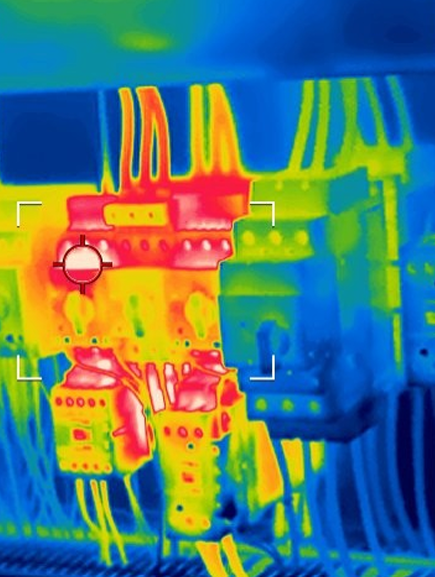
A loose electrical connection doesn’t usually announce itself. There’s no smell, no sound, no visible sign on the panel door. What it does is generate heat at the point of resistance, quietly, for weeks or months, long before anything trips or fails outright. The same goes for a bearing running under too much load or with too little lubrication. It gets hot before it seizes. In both cases, that heat is often the only early warning available, and it’s usually invisible or inaccessible until someone points a thermal imaging camera at it.
That’s the reason thermal imaging exists as a maintenance tool, and it’s worth understanding properly rather than just knowing the name.
What thermal imaging is
A thermal camera doesn’t see through anything. It detects infrared radiation coming off a surface and converts that into a visual thermal image, called a thermogram, where different temperatures show up as different colours. Most handheld units used for industrial inspection work use an uncooled thermal sensor, which is what makes them practical and affordable for routine site inspections rather than needing specialist cooled equipment. It’s worth being clear that this is a surface temperature reading, not an internal one. A component can be hotter inside than the surface shows, so the camera is reporting on what it can detect, not necessarily the full picture underneath.
Two things affect how reliable that reading is. The first is emissivity, which is how efficiently a surface tends to emit heat rather than reflecting it. Shiny metal has low emissivity and can give a misleadingly low reading, while a matte or painted surface reads more accurately. Anyone doing this properly accounts for the surface type before trusting the number.
The second is delta T, the temperature difference between a component and a comparable reference point, rather than the absolute temperature on its own. A connection running at 60 degrees might be completely normal, or it might be a serious fault, and the number alone doesn’t tell you which. What matters is how that reading compares to the equivalent connection on the same panel, or to what that component normally runs at. A ten degree difference between two identical connections on the same circuit is a far stronger signal than a single reading in isolation, and it’s the basis most competent thermography work is built on.
What it catches well, and what it doesn’t
It’s worth being straightforward about this, because thermal imaging sometimes gets sold as a catch-all, and it isn’t one.
It’s genuinely strong for electrical inspections. Loose or corroded connections, overloaded circuits, unbalanced phases, and failing components in switchgear and distribution boards almost all generate detectable heat before they fail, and a thermal inspection will detect that reliably. It’s also good on the mechanical side for anything already showing a temperature symptom, motor casings running hot, bearing housings starting to overheat, and it’s useful for spotting a blocked line or a fluid leak in pipework and heat exchangers, where a cold or hot patch on the outside of a pipe tells you something’s wrong with what’s moving through it.
Where it’s weaker is anything mechanical that hasn’t yet produced a measurable surface temperature change. A bearing developing a defect often shows up in vibration analysis well before it generates enough friction to register on a thermal image. By the time that same fault is visibly hot, it’s usually further along than the vibration data would have caught it. The two methods aren’t in competition, they’re picking up different signals at different stages, and a decent set of imaging sensors on a camera will only ever tell you about the stage that’s already producing heat.
That said, there’s a practical difference in how quickly and safely each method can be applied, and it’s worth factoring in. Vibration analysis needs a sensor placed on or near the machine, and on some sites that’s simply not possible. Multiple motors mounted high up on a structure, out of reach without access equipment, aren’t good candidates for handheld vibration readings, and fitting multiple wireless sensors to get around that is a real cost most sites won’t take on. Thermal imaging doesn’t have that problem. An engineer can stand on the ground, point the camera up, and compare all the temperatures within minutes. If one motor shows a step change against the others, that’s an immediate signal something’s happening there, without anyone needing to get near the machine.
Access and health and safety restrictions come into this more than people expect. Where equipment is difficult or risky to reach, working at height, confined spaces, live panels, thermal imaging is often the less invasive option, since it can be checked from a distance without shutting anything down or putting anyone near a hazard.
How much this matters comes down to how critical the equipment is and the environment it sits in. If a site holds spare motors and can swap them out, the priority isn’t necessarily fixing the one showing a fault straight away, it’s tracking it closely and having the replacement ready to go in before it actually fails. Thermal imaging fits that approach well, because it gives an early enough view of a developing problem to plan the swap on your own terms rather than reacting to a breakdown.
Oil condition monitoring sits alongside both again, picking up wear metals and lubricant degradation that neither vibration nor heat will show directly. Used together, the three cover a lot more ground than any one of them alone.
Who actually needs it, and who probably doesn’t yet
Thermal imaging earns its place fastest on sites with real electrical infrastructure, switchgear rooms, distribution boards, and panels feeding significant loads. It’s also a strong fit for plants running a lot of motors and drives, where an overheating casing or coupling is a common early failure sign. Sites that already carry out scheduled electrical inspections get extra value from adding thermal imaging on top, since it turns a visual check into a genuine diagnostic one, with proper temperature measurement behind the findings rather than a guess.
It matters less for small or simple installations where a routine visual and manual check already covers the realistic risk. Not every site needs a thermal imaging inspection programme, and a smaller operation without significant electrical load or critical rotating equipment may get little practical benefit from one beyond what standard inspection already covers.
What the process looks like with Pure
A one-off inspection is a sensible starting point, particularly for electrical systems that haven’t been checked before, or where you simply want a current baseline. An engineer inspects the panels, motors or pipework in question and flags anything running outside expected temperature ranges relative to comparable components.
Periodic inspection suits sites where conditions change over time, load increases, connections loosen, components age, and a single check won’t catch that drift. Regular inspections build a history that shows whether something is stable or getting worse, which changes how urgently it needs attention. Where we’ve inspected a site more than once, we’re looking out for trends as much as individual readings, and we bring that trend data into the report too, so you can see whether a hotspot is holding steady or moving in the wrong direction over time.
What comes back isn’t just a report with numbers on it. Alongside the thermal images, the annotated hotspots, and the priority rating, you get our read on what’s actually going on and what to do about it. If a motor is running hotter than it should, that’s the start of a conversation, not the end of one. We’ll ask how it’s been managed, when it was last lubricated, and whether load or duty cycle has changed recently, because those answers help us work out whether you’re looking at a lubrication issue, a component on its way out, or something else entirely. From there we can point you toward the right next step, whether that’s a process change, a lubrication schedule adjustment, or planning a replacement before it fails on you.
This runs as part of our wider Thermal Imaging service, and it fits naturally alongside vibration analysis and oil condition monitoring within the broader Pure Reliability programme, either as a standalone check or one strand of a fuller condition monitoring plan.
FAQ
How often should thermal imaging inspections be done? It depends on the equipment and how critical it is. Electrical systems are often inspected annually as a minimum, sometimes more frequently for high-load or high-risk panels. Mechanical equipment with a known heat risk might be checked on a similar schedule to other condition monitoring activities. The right frequency usually comes out of an initial assessment of the site and its risk profile.
Is thermal imaging the same as an electrical inspection? No, though the two are often done together. A standard electrical inspection checks compliance and physical condition. Thermal imaging adds a diagnostic layer on top, showing which connections and components are actually running hot under load, which a visual inspection alone won’t reveal.
Can thermal imaging replace vibration analysis? No, they catch different things. Thermal imaging picks up heat, which is often a later-stage symptom of a developing fault. Vibration analysis tends to detect mechanical faults earlier, before they’ve generated enough heat to register on a thermal camera. The two are complementary rather than interchangeable, and many reliability programmes run both.